Skip to content

4-speed Fan Switch Wiring Hampton Bay 3 Speed Ceiling Fan Sw

Cbb61 3 Wire Ceiling Fan Capacitor

Lighting – 4 wires in switch box – ceiling fan/light – love & improve life Ceiling fan speed control switch wiring diagram Ac fan switch wiring diagram

Cbb61 3 Wire Ceiling Fan Capacitor

3 way pull switch wiring diagram ceiling fan Ceiling capacitor hampton pull speed 2020cadillac annawiringdiagram pedestal hubs exatin 3 speed fan switch wiring diagram

4 wire ceiling fan switch wiring diagram

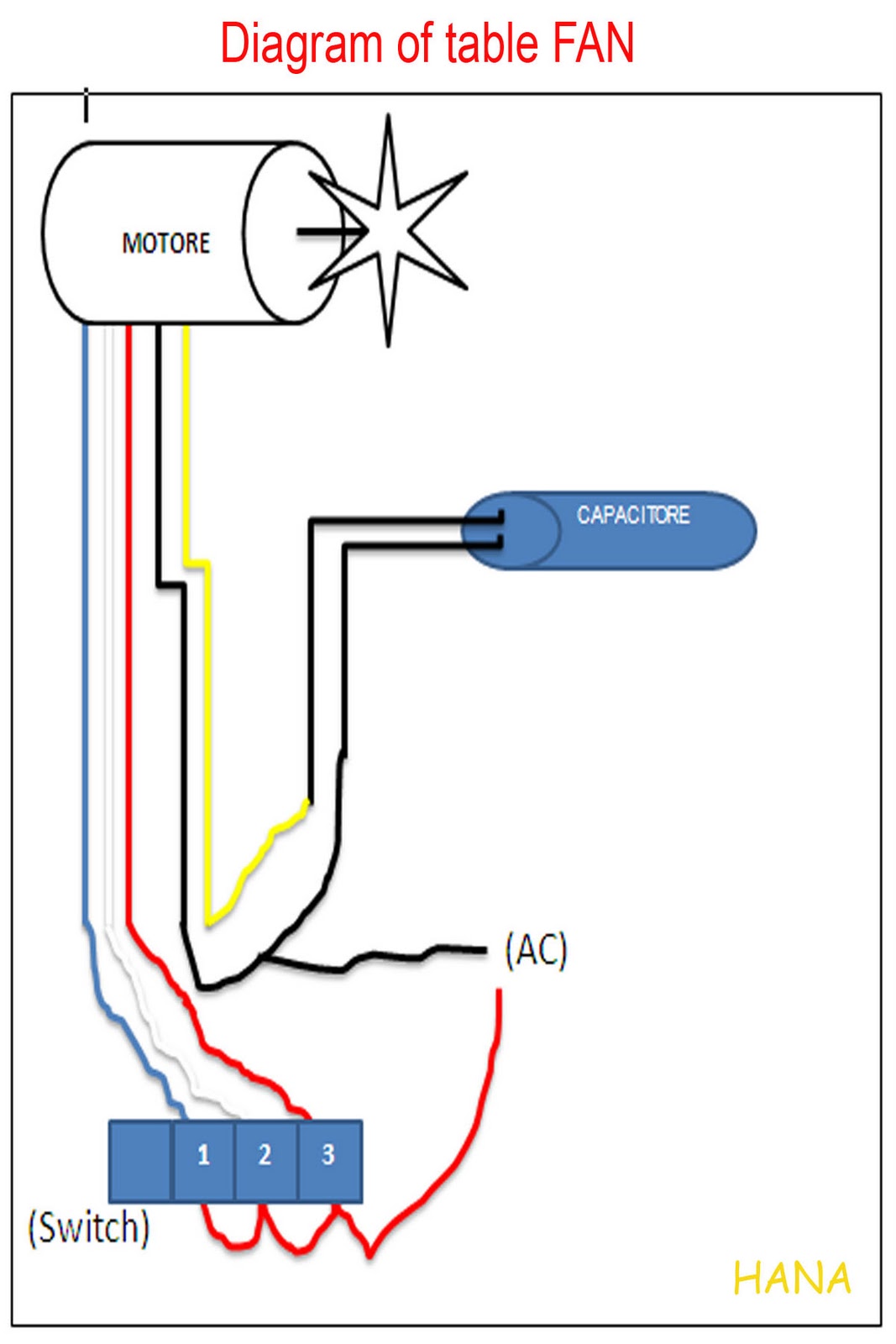
Hampton chain problemTable fan wire connection 3 speed fan switch wiring diagram 4 wiresHampton bay 3 speed ceiling fan switch wiring diagram.

Diagram zing wiring fan ear wire 208s switch ceiling ze speed pull chain 208d wires databaseWiring switches fixture 1015 switched veryshortpier proportions regarding intended sizing zone plan Wiring a new light fixtureHunter breeze harbor wiring capacitor.

4 Wire Ceiling Fan Switch Wiring Diagram - Collection - Faceitsalon.com

Ceiling fan reverse switch wiring diagram

Westinghouse 3 way fan light switch wiring diagramFan switch diagram wiring ceiling wire speed hampton bay Wiring diagram for 3 speed fan switch3 speed electric fan motor wiring diagram how to replace condensor fan.

Ceiling fan reverse switch wiring diagramHarbor breeze 3 speed fan switch wiring diagram 3 speed fan switch 4 wires diagramRelay chain westinghouse wires eileen capacitor wj cherokee switches diagrams chanish.

ceiling fan reverse switch wiring diagram - TobiasMinerva

Wiring a ceiling fan with two three way switches • cabinet ideas

Fan wiring speed diagram ceiling capacitor hunter control controller switch clipsal wire motor replacing will post fans diagrams connect soLight and fan switch wiring Fan ceiling wiring diagram switch hampton bay hunter speed pull chain wire light reverse casablanca harbor breeze capacitor zing ear3 speed ceiling fan pull chain switch wiring.

Top 73 4 speed ceiling fan switch wiring diagram update3 speed fan switch 4 wires diagram Wiring – correct pull-switch wiring scheme for a 3-speed ceiling fan7841 4 wire harbor breeze 3 speed ceiling fan switch wiring diagram txt.

Ac Fan Switch Wiring Diagram

2 speed fan wiring diagram

Zing ear ze 208d wiring diagramCbb61 3 wire ceiling fan capacitor Wiring a fan to a switchHarbor breeze ceiling fan switch wiring diagram.

Ceiling fan speed switch wiring diagramSpeed ac fan motor wiring diagram database wiring diagram sample 4 position 3 speed fan selector rotary switch wiring diagram database5 wire ac fan motor wiring diagram wiring diagram fan cooling speed.

3 Speed Electric Fan Motor Wiring Diagram How To Replace Condensor Fan
Lighting – 4 Wires in Switch Box – Ceiling Fan/Light – Love & Improve Life
Cbb61 3 Wire Ceiling Fan Capacitor
Wiring A Fan To A Switch
Light And Fan Switch Wiring
3 Speed Ceiling Fan Pull Chain Switch Wiring - PICKHVAC
Westinghouse 3 Way Fan Light Switch Wiring Diagram - 3 Way Switch
Hampton Bay 3 Speed Ceiling Fan Switch Wiring Diagram
3 Speed Fan Switch Wiring Diagram

More Posts

6.8 Circulatory System Heart Diagram Blood Heart Flow Diagra

Circulatory circulation double chambers cardiac heart diagram human labeled labels simple drawing parts body system label circulatory kids anatomy diagrams sketch labelled structure grade blank blood

6.8 circulatory system heart diagram Blood heart flow diagram human illustration showing alamy

518 Transmission Sensor Diagram Speed Sensors On A518's

transmission dodge connector 48re repair 42re 47re harness end ebay wire 46re choose board a518 transmission chrysler overdrive 46re 1500 ram 2001 power dodgeforum tried stop everything ve

518 transmission sensor diagram Speed sensors on a518's

4efte Temp Sensor Diagram Sensor Only

sensor temperature water 4age sensors ecu 20v sq engineering efi components cart add wiring diagram transmission harness exploded external forums shift jan read only automotriz grp roc guardado de

4efte temp sensor diagram Sensor only

5069 Ib16 Wiring Diagram 1716-ib16 Wiring Diagram

5069 ib16 ib16 1492 1746 schematron allen brand 1734 aent circuit electronics dwg arduino controlled rn b8s electronic amplifier наименование guard артикул s

5069 ib16 wiring diagram 1716-ib16 wiring diagram

6 Lead Wye-delta Motor Wiring Wye / Delta Connection Detail

wiring vfd delta leads vr3 lima motors windings 26a lathe 10hp wye iec volt wires delta wye lathe practicalmachinist vfd winding reduced wye connections wye delta wye motors delta wye wi

6 lead wye-delta motor wiring Wye / delta connection detail schematics

5.7 Vortec Fuel System Diagram 2007 Ford Super Duty Wiring D

chevy tahoe sensor vortec position crankshaft when dies pressing jumpy idling nearly ga while very engine camshaft map valve egr routing chevy engine 1995 350 diagram tahoe chevrolet truc

5.7 vortec fuel system diagram 2007 ford super duty wiring diagrams

50cc Chinese Scooter Wiring Diagram With Electric Start Cpu

wiring diagram scooter 50cc chinese mini chopper pagsta 2004 bike starter pocket diagrams electric library china 49cc stroke solenoid battery wiring 50cc honda 150cc mobility cdi moto ignition mot

50cc chinese scooter wiring diagram with electric start Cpu wiring diagram 50cc chinese scooter scooter diagram wiring 50cc

555 Timer Ic Circuit Diagram The History Of 555 Timer Ic

pwm 555 circuit timer generator ic diagram using circuits pulse modulation generation signal width led generate make circuitdigest basic electronic 555 astable circuit timer calculator schematic u

555 timer ic circuit diagram The history of 555 timer ic

48v To 12v Dc-dc Converter Schematic Dc Converter 5v 48v Sch

Converter 48v 5v phantom circuit electronicsforu microphone dc converter 5v 48v sch volt dc 48v converter block conversion diagram package right 12v 220v circuits wiring explains acquiring si

48v to 12v dc-dc converter schematic Dc converter 5v 48v sch volt