Skip to content

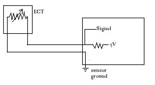
5.3 Coolant Temp Sensor Wiring Diagram Coolant Temp Sensor R

3 Wire Coolant Temperature Sensor Wiring Diagram - Making Sense Of The

3 wire coolant temperature sensor wiring diagram The overview of the engine coolant temperature sensor Coolant temperature sensor wiring diagram

3 Wire Coolant Temperature Sensor Wiring Diagram - Making Sense Of The

2 wire temp sensor coolant temperature sensor wiring diagram Coolant temperature sensor wiring diagram Temp sensor wire at joshua kaylor blog

Coolant temperature sensor?: first, i noticed my, page 2

Coolant temperature sensor wiring diagram – easy wiringCoolant temperature sensor wiring diagram database 3 wire temp sensor? & otherWiring diagram of engine cooling temperature sensor (ect), and its.

Coolant temperature sensor wiring diagram awesomeCan i get a coolant temperature sensor wiring diagram? [diagram] map sensor wiring diagram engine full version hd qualityCoolant temperature sensor wiring diagram.

Coolant Temperature Sensor Wiring Diagram

Coolant temperature sensor wiring diagram.

How to connect the coolant temperature sensor with a wiring diagramCoolant temp sensor reading low [diagram] pt100 temp sensor wiring diagram1, 2 & 3 wire coolant temperature sensor wiring diagram.

[diagram] 2 wire temp sensor coolant temperature sensor wiring diagramDiagram coolant How to wire up a temp sensor at madeleine wade blog[diagram] dummy light wiring diagram temperature sensor.

2012 Ford Fusion Coolant Temperature Sensor Location

3 wire coolant temperature sensor wiring diagram

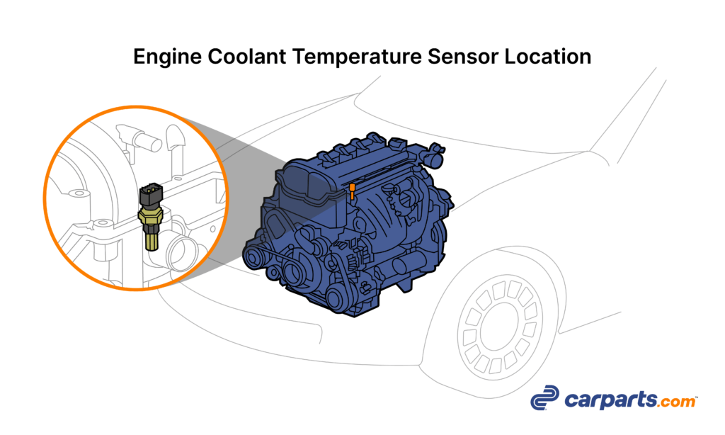
3 wire coolant temperature sensor wiring diagram3 wire coolant temperature sensor wiring diagram Sensor coolant temperature location temp diagramsCoolant temperature sensor location and wiring diagrams?.

As one of the online sales mall engine coolant temperature sensor-autoCoolant temperature sensor wiring diagram database 2012 ford fusion coolant temperature sensor locationCoolant temperature sensor wiring diagram – easy wiring.

[DIAGRAM] Pt100 Temp Sensor Wiring Diagram - MYDIAGRAM.ONLINE
[DIAGRAM] Pt100 Temp Sensor Wiring Diagram - MYDIAGRAM.ONLINE

Smart coolant temperature sensor system circuit with a closed-looped

[diagram] 2 wire temp sensor coolant temperature sensor wiring diagramCoolant temperature sensor wiring diagram Coolant temperatureCoolant temp sensor wiring diagram.

.

Coolant Temperature Sensor?: First, I Noticed My, Page 2
Wiring Diagram of Engine Cooling Temperature Sensor (ECT), and its
3 Wire Coolant Temperature Sensor Wiring Diagram - Making Sense Of The
3 wire Temp sensor? & other - Third Generation F-Body Message Boards
Coolant Temperature Sensor Wiring Diagram Database
Coolant Temp Sensor Wiring Diagram | My XXX Hot Girl
Coolant Temperature Sensor Wiring Diagram Awesome | Wiring Diagram Image
Coolant temperature sensor wiring diagram

More Posts

4th Generation Rear Brake Diagram Brake Upgrades 4th Gen Leg

brake brakes ford rear ranger diagram 2000 find 1999 drum 4x4 online repair shoe if justanswer v6 wheel opposite removed disadvantages hydraulic carbiketech rear brakes ram wheel 1998 1500 wrangler

4th generation rear brake diagram Brake upgrades 4th gen leg

5 Wire Emerson Thermostat Wiring Diagram Emerson Sensi Therm

Wiring thermostat diagram heater gas furnace wall hvac diagrams old room modine wire manual heat systems ac dimplex honeywell valve wiring thermostat rodgers diagram white emerson wire heat pump

5 wire emerson thermostat wiring diagram Emerson sensi thermostat wiring diagram

5 Sector Circular Flow Model Diagram Economy Flow Circular S

sector flow model circular sector economy flow circular sector diagram business government system three income infographic infographics markets households example trade concep

5 sector circular flow model diagram Economy flow circular sector diagram business government system three income infographic infographics markets households example trade conceptdraw solution international labor

48 Volt To 12 Volt Reducer Wire Diagram 36/48 Volt To 12 Vol

converter 5v 48v circuit input cart golf volt 48 diagram wiring rtv club car quite sitting while been has reducer golf fuse memory radio dc unlimited carts 12v voltage reducer precedent bat

48 volt to 12 volt reducer wire diagram 36/48 volt to 12 volt voltage converter/reducer with key switch/ trigg

555 Timer Schematic How To Build Vco With 555 Timer

555 timer circuit monostable breadboard build resistance schematic using calculate total do comments auto diagram led chaser 4017 555 capacitor circuit timer using wiring counter motor run start of

555 timer schematic How to build vco with 555 timer

5 Wire Rocker Switch Diagram [diagram] Momentary Rocker Swit

rocker carling lighted illuminated toggle diagrams momentary switches 12v volt chanish bep tabs lamp positions switch rocker led light wiring diagram bar toggle dorman volt off electrical automotive

5 wire rocker switch diagram [diagram] momentary rocker switches 12v winch wire diagram

5 Wire Trailer Diagram 4 Wire Trailer Wiring Diagram Pdf

trailer wiring wire diagram plug way connector harness power prong connectors weebly collection fiat ignition a8 trailers flagstaff plug wesbar wiring wishbone chanish connectors marineengine

5 wire trailer diagram 4 wire trailer wiring diagram pdf

555 Pwm Circuit Diagram How To Generate Pwm Using Ic 555 (2

Pwm circuits generating generate explored configuration simplest pwm motor dc controller circuit ne555 diagram transistors darlington 555 dimmer led power using transistor voltage generator switch ele

555 pwm circuit diagram How to generate pwm using ic 555 (2 methods explored) – homemade

5x A4988 Stepper Motor Driver Module Diagram A4988 Stepper W

5x a4988 stepper motor driver module diagram A4988 stepper wiring specification