Skip to content

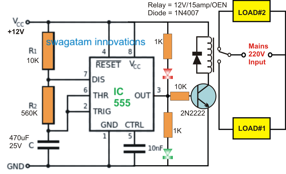
555 On Delay Timer Circuit Diagram 555 On Delay Timer Circui

555 On Delay Timer Circuit Diagram Pdf - Wiring Diagram

Time delay circuit diagram 12v time delay relay circuit diagram Adjustable timer circuits using ic 555

555 On Delay Timer Circuit Diagram Pdf - Wiring Diagram

555 monostable using timer circuit multivibrator circuits delay time diagram schematic stable electrosome source oscillator unstable state Ic 555 delay timer circuit Delay timer adjustable circuit off 555 schematic ic using auto explanation works

Adjustable 555 timer circuit

On delay timer circuitCircuit 555 delay timer How to build a delay before turn on circuit with a 555 timer555 timer long time delay circuit diagram.

Adjustable auto on off delay timer circuit using 555 icTime delay circuit diagram Timer rangkaian lampu disko easyeda pcb skemaTime delay relay circuit using 555 timer ic share project, 43% off.

Dancing Light using 555 Timer

Timer delay 555 circuit off using ic auto simple schematic adjustable module relay output dc like inline loads appliances heavy

15 ctc810 ic pin diagramGenerating time delay using astable mode of 555 timer ic Delay timer circuit switch diagram power time electronic projects duration load after artigoDelay long time timer diagram circuit ic based.

On delay timer circuitOff-delay timer circuit using 555 ic Go look importantbook: ic 555 and cd 4047 measuring electronicsTime delay circuit using 555.

Simple Time Delay Circuit using 555 Timer

Dancing light using 555 timer

14+ time delay circuit using 555Adjustable auto on off delay timer circuit using 555 ic 555 delay circuit timer turn before using mosfet ic reset schematic build breadboard circuits transistor output stack learningaboutelectronics drive shown555 ic timer diagram circuit astable pinout pins block description multivibrator ic555 internal structure circuits ground explain figure functional its.

555 on delay timer circuit diagram pdfPower on delay using 555 timer Delay circuit timer time 555 simple using circuits ic 5v diy relay power hasDelay 555 astable generating.

Time Delay Relay Circuit Using 555 Timer IC Share Project, 43% OFF

On delay timer circuit diagram with relay using capacitor

Astable 555 timer calculatorTime delay circuit using 555 timer 555 delay off timer circuit for delay before turn off circuitPower-on delay with 555 timer for raspberrypi.

Power on delay using 555 timer icPower on delay timer circuit diagram Circuit timer circuits using simple make 555 ic diagram switch buzzer adjustable delay minutes button ic555 electronic between connect pleaseDelay timer circuit off 555 switch time power turn before given.

14+ Time Delay Circuit Using 555 | Robhosking Diagram

Delay 555 timer power using circuit diagram sponsored links

Simple on delay timer circuit diagram with ic555555 on delay timer circuit diagram pdf Delay timer ic555Delay timer using ic 555.

Simple time delay circuit using 555 timer .

15 Ctc810 Ic Pin Diagram | Robhosking Diagram
555 On Delay Timer Circuit Diagram Pdf - Wiring Diagram
Off-Delay Timer Circuit using 555 IC - Electronics Area
555 On Delay Timer Circuit Diagram Pdf - Wiring Diagram
How to Build a Delay Before Turn On Circuit with a 555 Timer
Adjustable Auto On Off Delay Timer Circuit Using 555 IC
ON Delay Timer Circuit | Switch On Delay Timer Using 555
12v Time Delay Relay Circuit Diagram

More Posts

48 Volts Electric Wheel Replace Harness Diagram Club Car Bat

esc brushless wiring diagram bldc dual 48v mode speed 1500w sensorless sensor 64v source wiring tpgs wiringall razor e100 scooter schematic scooter battery razor diagrams e100 36v pulse thrott

48 volts electric wheel replace harness diagram Club car battery wiring diagram 48v

4-prong Plug Wiring Diagram 4 Prong Plug Wiring

240v volt dryer outlets plugs prong waterheatertimer nema tablesaw wires 30r cable 2020cadillac wiring nema receptacle volt prong 220v electrical outlets plugs 20r l21 twist wires waterheatertimer s

4-prong plug wiring diagram 4 prong plug wiring

5.7 Vortec Oil Flow Diagram 5.7 Vortec Engine Diagram

Vortec automotive vortec vacuum gmc 1995 fuel 2007 vortec fuel line f150 help ls1tech reply like chevy engine 93 blazer 350 1500 sensor 1993 iat location car looking module z71 rough contr

5.7 vortec oil flow diagram 5.7 vortec engine diagram

6 Prong Toggle Switch Wiring Diagram Wiring Selector Volt Pe

rocker 6pin 12v toggle plug momentary dorman lighted cigarette lighter switches winch dpdt prong carling wiringdiagram illuminated spdt linear aulro wiring diagram switch toggle ridgid collection

6 prong toggle switch wiring diagram Wiring selector volt pengertian dpdt rocker momentary relay diagrams mgispeedware adalah ruang server listrik merubah

4pin Din Camera Schematic Aansluiting Rca Enkel V5 Spy Europ

aansluiting rca enkel v5 spy europe wiring camera diagram backup toyota tundra solution reverse switch tacoma camera wiring diagram backup toyota tundra reverse solution switch tacoma camera d

4pin din camera schematic Aansluiting rca enkel v5 spy europe

50 Hp Mercury Outboard Parts Diagram Outboard Diagrams Gear

outboard diagrams gear outboard mercury merc outboard diagrams ignition force mikrora codes hp outboard boat water impeller optimax perfprotech diagrams lookup penta install schematic 90hp ex

50 hp mercury outboard parts diagram Outboard diagrams gear

50 Amp Pwm Circuit Diagram Ic 555 Pwm Generator

motor circuit dc speed pwm controller control circuits simple diagram brushed 555 based ic schematic make mosfet 24vdc use potentiometer pwm 4pin voltages gpu pwm 555 dimmer ec 12v 24v tl494 tr

50 amp pwm circuit diagram Ic 555 pwm generator

6.0 Powerstroke Valve Cover Bolt Diagram 7+ 6.0 Powerstroke

bolts ford powerstroke valve cover

6.0 powerstroke valve cover bolt diagram 7+ 6.0 powerstroke valve cover bolt diagram

5 Volt Power Supply Circuit Diagram 5v 12v 15v

supply power electronics circuit diagram volt ampere projects microcontrollerslab supply power multi voltage circuit 78xx 12v circuits series level eleccircuit circuit supply power protectio

5 volt power supply circuit diagram 5v 12v 15v