Skip to content

5v Boost Converter Schematic Diy Tiny 5v / 2a Boost Converte

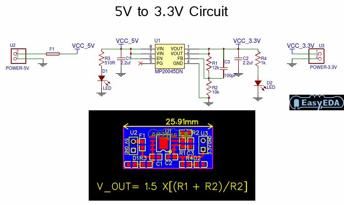
5V to 3.3V Converter Circuit - Electronic Circuit

Simple voltage booster circuit using transistors Boost converter schematic diagram 5v to 3.3v converter circuit

5V to 3.3V Converter Circuit - Electronic Circuit

5v boost converter module circuit diagram 1.5v to 5v boost converter circuit for micro computer 3.7v to 5v boost converter using me2108 ic

A simple dc-dc boost converter circuit using 555 timer ic

12v to 5v converter circuit diagramSchematic_5v boost resources 3.7v to 5v boost converter using me2108 icBoost converter (1,5v dc to 5v dc).

How to make a simple and powerful to 12v boost converter5v circuit converter 3v schematic layout module pcb 3v to 5v 2a boost converter circuit diagram5v converter boost diagram circuit output 2a diy.

Best 3.7v to 5v Boost Converter Circuit & Module - SM Tech

3.7 v to 5v converter circuit diagram

3.7v to 5v boost converter me2108a33p3.7v to 5v boost converter circuit diagram using mc34063 Boost converter dc diagram circuit input step schematic using electronoobs output circuitos make homemade feedback component boots choose board capacitorConverter boost circuit 5v 7v using diagram circuits components required.

3v to 5v 1a boost converter circuit diagramDiy tiny 5v / 2a boost converter (simple) Dc to dc boost converter circuit homemade1.5v to 5v boost converter circuit for micro computer.

5V Boost Converter
5V Boost Converter

Boost converter 5v using circuit diagram

Boost converter circuit using 555 timer ic1.5 v to 5 v voltage boost converter circuit easy diagram Boost converter schematic diagramSchematics of buck converter.

5v boost converterCircuit converter diode 5v input capacitor zener Converter circuit 5v 12v basic eleccircuit flasher kerja induction heater vapcap5v boost converter.

5V Boost Converter
5V Boost Converter

5v boost converter circuit to generate 5v from single cells

Converter 5v circuit schematic1.5v to 5v boost converter circuit for micro computer 5v boost converterConverter 5v micro circuit boost dc step computer eleccircuit 12v battery voltage diagram circuits power output electronic convert charger 2v.

Converter boost circuit 5v step micro computer choose board5v converter circuit electronic 5v converter buck converters electricaltechnologyConverter boost working 5v block diagram.

5v To 12v Boost Converter Circuit Diagram

5v boost converter module circuit diagram

Circuit dc converter boost inductor build shown below breadboard above pdfBest 3.7v to 5v boost converter circuit & module 12v to 5v converter circuit5v to 12v boost converter circuit diagram.

Booster transistors circuits explanationHow to build a dc-to-dc boost converter circuit Boost converter schematic diagram.

3.7V to 5V Boost Converter Circuit Diagram using MC34063
1.5 V To 5 V Voltage Boost Converter Circuit Easy Diagram
5v Boost Converter Module Circuit Diagram
How To Make A Simple And Powerful To 12V Boost Converter
Boost Converter Schematic Diagram
3v To 5v 2a Boost Converter Circuit Diagram - Circuit Diagram
5V to 3.3V Converter Circuit - Electronic Circuit
3.7V to 5V Boost Converter using ME2108 IC

More Posts

50988 Ignition Switch Wiring Diagram Key Switch Wiring Diagr

ignition mower indak diagrams msecnd vo toro relay wiring ignition starter solenoid polaris ignition ranger sportsman mower ignition tractor westwood craftsman briggs stratton t1200 s

50988 ignition switch wiring diagram Key switch wiring diagram diagrams schematics and starter

50 Inch Light Bar Wiring Harness Rough Country 50 Inch Led L

bar light harness wiring led tweet agrisupply duty light wiring harness heavy bar light bar led windshield wiring bars our offroad added knew whole lighting were things next headliner kc lights

50 inch light bar wiring harness Rough country 50 inch led light bar upper windshield kit for 18-23 jeep

4th Generation Ram 1500 Radio Diagram Wiring Dodge Charger P

wiring ram dodge stereo 2001 diagrams manual service 1995 wiring dodge charger pinoutguide 300c wiring stereo durango cargurus chanish harness chrysler autozone ram schematic ram justanswe

4th generation ram 1500 radio diagram Wiring dodge charger pinoutguide 300c

5.9 Cummins Fuel Filter Housing Diagram Cummins Housing 24v

Housing cummins fuel filter diesel enlarge click oem dodge 9l mopar genuine assembly factory cummins fuel diagram engine oil flow system marine 6bta diesel 370 330 pump cooling cooler diamond sea

5.9 cummins fuel filter housing diagram Cummins housing 24v 9l enlarge

6 Pin Toggle Switch Wiring Diagram Datasheet Wiring And Togg

Switch toggle wiring rocker switches prong dpdt switching electrical momentary gps trasig reverse prong rocker switches circuit automotive electronics switching wires trasig wiring

6 pin toggle switch wiring diagram datasheet Wiring and toggle switch. basic electrical wiring, electrical circuit

5 Switches One Power Source Diagram Is This A Proper Schemat

switching 5v 10a offline 50w output schematic circuits flyback switched voltage diagram romex switches circuit fixture schematic 5v electronics power supply switching 3a lab circuit v

5 switches one power source diagram Is this a proper schematic for a power switch between two 5v sources

5 Wire Single Phase Capacitor Start Motor Wiring Diagram 120

Wiring 220v capacitor correct diagrams capacitor 230v diagrams vac hubs cscr drum ge vfd 2020cadillac capacitor start motor wiring diagram run phase single capacitor phase doerr 220v circuit in

5 wire single phase capacitor start motor wiring diagram 120 volt ac wiring diagrams

4-wire Dual Ceiling Fan Dimmer Switch Wiring Diagram How To

Fan ceiling wire connection four ceiling fan capacitor replace connect switch circuit capacitors power replacing ways supply capacitor wiring electricaltechnology switch electrical ceiling dimmer r

4-wire dual ceiling fan dimmer switch wiring diagram How to replace a capacitor in a ceiling fan? 3 ways

6.0 Icp Sensor Pigtail Wiring Diagram 7.3 Icp Sensor Pigtail

pigtail camshaft powerstroke 0l 4ft cps 4l icp wiring diagram sensor ford circuit wire vref forums codes low 2007 location reply truck trucks like

6.0 icp sensor pigtail wiring diagram 7.3 icp sensor pigtail wiring diagram